

Tyler Anderson, Technical Specialist at MatterHackers, takes you thru the method of his creation- The Computerized Print Ejector. This system will increase your 3D Printer’s autonomy by eradicating your accomplished prints off your print mattress by punching them with a boxing glove.
Posted on December 18, 2015
by
MatterHackers
The aim of this system is to take away completed objects from the printer in probably the most amusing Rube Goldbergish method attainable. The unique plan was to have a boot swing down and kick the half up and about, however we determined {that a} boxing glove could be extra hilarious. It’s impressed by comparable issues from outdated cartoons.
The Computerized Print Ejector is made solely from printed elements and issues we had laying round within the warehouse of MatterHackers. The printer being victimized is an OpenBeam Kossel Professional.
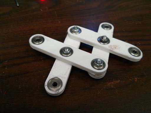
I began off by rapidly designing some linkages in Solidworks. The holes match some little ball bearings we had laying round. Every thing is held along with M3 bolts. We had an assortment of various sized bearings, so I needed to design elements with a pair totally different gap sizes. All the ones posted on-line are made to suit 9.5mm outer diameter bearings. The holes additionally embody an additional 0.3mm to account for the tolerances of printing.
This was a enjoyable challenge as a result of most elements took lower than half-hour to print. I could possibly be designing the following factor whereas the final piece was printing. There was no ready. In some instances its higher to plan every part out originally earlier than you construct it, however it may be extra enjoyable to only dive in and determine issues out as you go alongside. That is what I did with this challenge. I ended up with plenty of trashed elements, however who cares.
Every thing was printed in PLA since I used to be not fearful about something getting heat.
Really useful Print settings:
- 0.2 mm Layers
- 2 Perimeters
- 30% Infill
As a way to actuate the scissor mechanism, I added a gear to the tip of one of many linkages. I additionally discovered an outdated stepper motor to drive it. I might have used a passion servo, however the stepper is what we had and its acquired extra torque in any case. It additionally conveniently had a small gear already on the shaft.

That is the bracket I designed to carry the motor and every part. The plan was that your entire system would jut out from the facet of the printer, supported by a size of OpenBeam. As you may see, engineering is an iterative course of.


At this level it turned obvious that solely driving one linkage would not work. The whole meeting would simply rotate down as a substitute of extending outward. Each of the tip linkages have to be pressured collectively or pulled aside to ensure that the mechanism to work. I added a second gear with inward dealing with enamel. This manner it will be pushed in the other way, forcing the linkages collectively.

Because the gears have totally different radiuses, there are barely totally different gear ratios and one linkage strikes barely farther than the opposite. This makes the entire thing rotate downward just a few levels when it extends. Oh nicely. Its adequate.
The boxing glove mannequin was discovered by way of googling and I modified it in Blender with a sq. gap within the backside to attach it to the arm. This glove turned out to be probably the most troublesome factor to print. Not as a result of it’s a sophisticated form, however purely due to a collection of unlucky coincidental points with the printer (a few of which concerned fireplace). When it lastly did print, the help construction underneath the fingers failed, so it does not have fingertips. I made a decision I do not care since you will not see that facet a lot in any case.

That is once I bumped into the following drawback. How do you retain the boxing glove horizontal? I designed a fork formed factor that may slide over the bolts within the heart of the linkages. This makes positive that no matter is connected to the tip stays parallel to the mechanism.

Final step was to connect the beam to the underside and bolt it onto the facet of the printer.
I needed to design some nook brackets as nicely so as to join the beam to the printer’s body. The mattress is in the best way so I couldn’t use the official OpenBeam T-Brackets. Luckily I remembered to place some additional nuts within the beams once I was constructing the printer. As a result of the factor is mounted perpendicularly on one facet, it punches the objects straight into the tower on the alternative facet. Finally I’ll make some 30 diploma / 60 diploma nook brackets so it is going to punch in the suitable path.
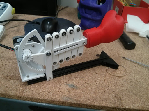
The 24 cm beam is simply barely lengthy sufficient. The print head narrowly misses the glove whereas doing the auto-calibration routine and bumps into it just a little bit when printing all the best way out to the perimeters.

The completed product.
COMPONENT LIST (What you will have)
Wiring was fairly simple. I salvaged an outdated Pololu stepper driver from certainly one of our spare RAMPS boards and used a ribbon cable with feminine headers to wire it as much as the Brainwave. Right here is the the wiring diagram from Pololu:
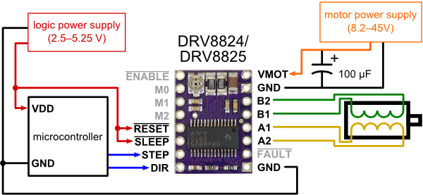
I used the 12V rail from the Brainwave for VMOT versus the 24V rail from the Kossel’s PSU. Undecided how a lot present the 12V line was meant for, nevertheless it appears to be doing all proper. The STEP, DIR, and EN strains are hooked as much as OC1B, OC1C, and OC1A, respectively. I did not trouble with microstepping as a result of I needed as a lot torque as attainable. A pullup resistor on the EN line is perhaps a good suggestion however I did not embody it. Right here is the pin configuration added to the Brainwave Professional part of pins.h. I needed to dig round in Arduino’s pins_arduino.h to seek out the corresponding pin numbers.
#outline PUNCH_STEP_PIN 26     // OC1B
#outline PUNCH_DIR_PIN 27      // OC1C
#outline PUNCH_ENABLE_PIN 25   // OC1A
The motor I discovered already had a connector on the tip of it, however once I plugged it in it did not wish to work. I verified the motor connections utilizing an outdated trick. In case you leap two of the strains collectively and the motor turns into tougher to show, you understand they’re related to the identical coil. Rearranged the pins on the connector and every part was good.
The programming can be not sophisticated. I am together with the attention-grabbing elements right here however the total factor is offered on GitHub. The firmware relies on the OpenBeam department of Marlin firmware. The adjustments shouldn’t be laborious to patch into some other department of Marlin, although.
I added a brand new G-Code command (G42) that prompts the punching mechanism. It additionally accepts a feedrate (in Hz) so you may inform it how briskly to punch. For instance, “G42 F300”. If you don’t set a velocity, it defaults to 50 steps/s. Right here is the part from the G-Code parser in Marlin_main.cpp:
    case 42: // G42
      if(code_seen('F')) {
        punch(code_value());
      } else {
        punch(50);
    }
That is the precise punching code in pugilism.cpp.
void punch(float velocity)
{
  int delayLength = 1000 / (velocity*2);
  SERIAL_ECHOLN("WHAM!");
  // Allow driver
  digitalWrite(PUNCH_ENABLE_PIN, LOW);
  // Set path
  digitalWrite(PUNCH_DIR_PIN, HIGH);
  // Punch
  // Concept: Ramp up velocity
  for (int i=0; i<150; i++) {
    delay(delayLength);
    digitalWrite(PUNCH_STEP_PIN, HIGH);
    delay(delayLength);
    digitalWrite(PUNCH_STEP_PIN, LOW);
  }
  // Reverse path
  digitalWrite(PUNCH_DIR_PIN, LOW);
  // Retract
  for (int i=0; i<150; i++) {
    delay(10);
    digitalWrite(PUNCH_STEP_PIN, HIGH);
    delay(10);
    digitalWrite(PUNCH_STEP_PIN, LOW);
  }
  // Disable driver
  digitalWrite(PUNCH_ENABLE_PIN, HIGH);
}
Mainly it prompts the driving force, sends 150 pulses to the step pin, then reverses and disables the driving force. 150 steps appears to be about the suitable distance for the reason that stepper motor has 200 steps/revolution and I might inform from shifting the linkage by hand that the gear rotates about 3/4 of a flip.
300 steps/s appears to be the best velocity. It’s fast and forceful, however not so quick that it overloads the stepper motor. Typically it skips steps whereas punching however that is high-quality as a result of it resets its place when it retracts. I had an concept that you might get extra energy by accelerating as a substitute of punching at a relentless velocity. This would not be laborious to implement however I have never achieved it but.
Take a look at the challenge web page at hackaday.io for future updates to this challenge.
Glad Printing Punching!